This tutorial will show you how to decode USB Data for implementing devices in SignalRGB.
If you do not already have a data capture check out our tutorial for capturing USB data.
Sorting Data
Before we can try to interpret the USB Data Capture we'll want to sort it to find some specific packets.
In Wireshark:
- Open the USB Data Capture
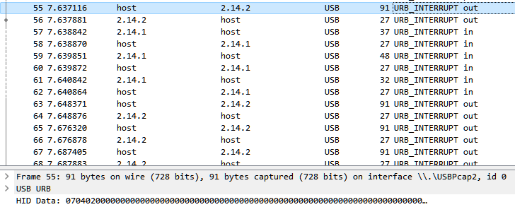
- Click on the 'Info' header to sort by packet type
- Scroll through until you find either a URB_INTERRUPT OUT or SET_REPORT Request type
If you do not find either of the above commands, you may either be working with a RAWUSB device or you may not have done the capture correctly. If you have a RAWUSB device, you will see URBBULK_OUT or URB_CONTROL OUT commands. If you have a RAWUSB device, join this discord server for development help.
Finding RGB Packets
The packets that we are going to be looking for first are ones that contain the RGB values that we set when taking our USB packet captures.
Note: We are purposefully going to ignore device initialization packets for now. These may be required later.
The data being sent in each packet comes after all of the USB protocol header info. To see this we'll need to find the Data Fragment section.
- Select a packet
- Select the HID Data field or Expand the Setup Data section and select the Data Fragment field
- Clicking on the field should also highlight the data section in blue at the bottom of Wireshark
- The selected field will also show the data sent without spacing. Every 2 characters is a single byte in this view.
Note: The values that we are looking at are going to be in HEX (base 16) which is a data format that represents 0 to 255 in decimal as values of 0x00 to 0xFF.
Packet Structure
Since we set red, green, and blue to their maximum values in our USB Data Capture guide, we are going to be looking for values of 0xFF in our packet capture. If you used different colors in your capture you'll need to know the specific HEX color used or to recapture with known colors.
Traditionally the lighting packets for a device contain a header that signifies what command the packet is for and which lighting zone of a device we are addressing followed by the RGB data and rarely some footer data like a CRC checksum.
The RGB data commonly follows a few formats which we can check by looking for the colors that we set in our capture:
- R, G, B, R, G, B, R, G, B (Red -> Green -> Blue -> Repeat)
- RRR, GGG, BBB (Several Red -> Several Green -> Several Blue -> Repeat)
- Br, R, G, B (Brightness -> Red -> Green -> Blue -> Repeat)
Note: Some devices will use a different color order. While most use RGB you may find that your device uses GBR, BGR, or another combination.
In our case, the values that we're looking for will be:
- 0xff, 0x00, 0x00 | 0x00, 0xff, 0x00 | 0x00, 0x00, 0xff (if the device uses the R,G,B packet order).
- 0xff, 0xff, 0xff, 0x00, 0x00, 0x00, 0x00, 0x00, 0x00 (if the device uses RRR,GGG,BBB packet order).
- 0xff, 0xff, 0x00, 0x00 | 0xff, 0x00, 0xff, 0x00 | 0xff, 0x00, 0x00, 0xff (if the device uses Br,R,G,B packet order)
Note: The above examples are just some common packet structures for devices, and may not always apply. you'll need to compare and look for similarities.
Checking Packets
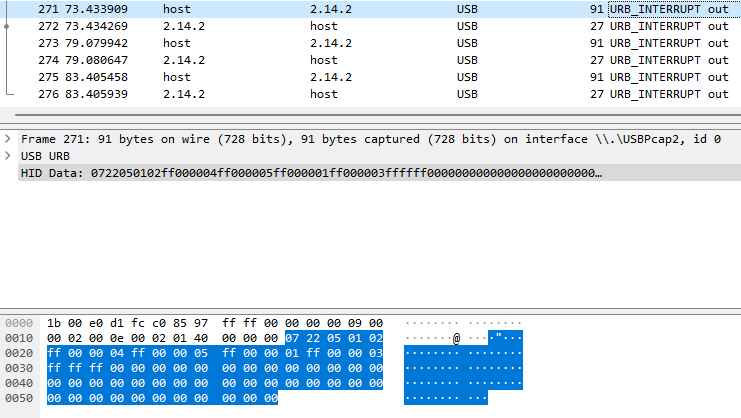
Scrolling down through the packets we find that packet 271 in our capture contains bytes that look similar to the R,G,B packet structure.
Note: Some devices may use multiple packets to set the colors on the entire device. Make sure you look at the next packets and make sure you find where the initial packet repeats.
We're going to mark this packet by using the MARK/UNMARK Packet function in Wireshark, which can be done by pressing the CTRL + M keys simultaneously or right clicking the packet and clicking MARK/UNMARK Packet.
To confirm that this packet is actually one of our color data packets, we're going to keep scrolling down to look for more packets that fit our R,G,B structure. We're also going to see if these packets follow the order we set colors in the original software. This is good time to look at the headers of the packets and see if they change. If they are changing in a pattern it's highly likely you'll have multiple packets needed to set all LEDs on the device.
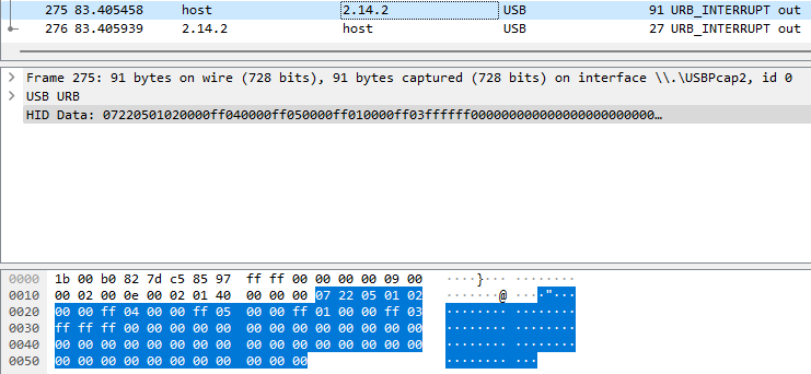
Taking a look at packet 271, packet 273, and packet 275 side by side, we can see that the RGB data looks to be only Red on packet 271 (0xFF, 0x00, 0x00), only Green on packet 273 (0x00, 0xFF, 0x00), and only Blue on packet 275 (0x00, 0x00, 0xFF). Looking at the header data above the RGB section we can see that this data does not change between the three packets. This most likely means that we are changing the same color zones in these packets.
- Also of note, we can use the color packets to determine how many zones a device contains. We can find this by checking how many times our known values occur in the RGB data packets. Looking at the example below, we see that the device has 4 zones that we can definitely address.

We are going to keep going down through our packets until we find all of the packets that contain color data and have marked them. After that we'll move on to creating our plugin file.